

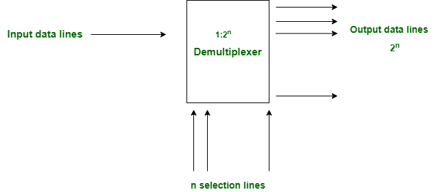
A demultiplexer (DEMUX) is a combinational logic circuit that routes a single input to one of several output lines using select lines. It performs the reverse operation of a multiplexer (MUX).
- A DEMUX has one data input, multiple output lines, and select lines.
- The select lines determine which output line receives the input signal.
Types of DEMUX
The DEMUX can be classified based on the number of output lines. The two commonly used types are:
- 1 × 4 DEMUX
- 1 × 8 DEMUX
1×4 DEMUX
A 1×4 DEMUX is a combinational circuit with one input (I), two select lines (S₁, S₀), and four outputs (Y₀–Y₃). The select lines determine which output receives the input signal.
Block Diagram and Truth Table of 1×4 DEMUX
The block diagram shows one input (I), two select lines (S₁, S₀), and four outputs (Y₀–Y₃). Depending on the values of the select lines, the input is routed to one output while the remaining outputs stay LOW.

The truth table of a 1×4 DEMUX is shown below.
| Selection Inputs | Outputs | ||||
|---|---|---|---|---|---|
| S1 | S0 | Y3 | Y2 | Y1 | Y0 |
| 0 | 0 | 0 | 0 | 0 | I |
| 0 | 1 | 0 | 0 | I | 0 |
| 1 | 0 | 0 | I | 0 | 0 |
| 1 | 1 | I | 0 | 0 | 0 |
1×8 DEMUX
A 1×8 DEMUX has one input, three select lines (S₂, S₁, S₀), and eight outputs (Y₀–Y₇). The select lines choose which output receives the input signal.
Block Diagram and Truth Table of 1×8 DEMUX
The block diagram consists of one input (I), three select lines (S₂, S₁, S₀), and eight outputs (Y₀–Y₇). The binary value of the select lines determines which output receives the input signal.

The truth table of a 1×8 DEMUX is shown below.
| Selection Inputs | Outputs | |||||||||
|---|---|---|---|---|---|---|---|---|---|---|
| S2 | S1 | S0 | Y7 | Y6 | Y5 | Y4 | Y3 | Y2 | Y1 | Y0 |
| 0 | 0 | 0 | 0 | 0 | 0 | 0 | 0 | 0 | 0 | I |
| 0 | 0 | 1 | 0 | 0 | 0 | 0 | 0 | 0 | I | 0 |
| 0 | 1 | 0 | 0 | 0 | 0 | 0 | 0 | I | 0 | 0 |
| 0 | 1 | 1 | 0 | 0 | 0 | 0 | I | 0 | 0 | 0 |
| 1 | 0 | 0 | 0 | 0 | 0 | I | 0 | 0 | 0 | 0 |
| 1 | 0 | 1 | 0 | 0 | I | 0 | 0 | 0 | 0 | 0 |
| 1 | 1 | 0 | 0 | I | 0 | 0 | 0 | 0 | 0 | 0 |
| 1 | 1 | 1 | I | 0 | 0 | 0 | 0 | 0 | 0 | 0 |
1×16 DEMUX
A 1×16 DEMUX is a combinational circuit with one input (I), four select lines (S₃, S₂, S₁, S₀), and sixteen outputs (Y₀–Y₁₅). The select lines determine which output receives the input signal.
Block Diagram and Truth Table of 1×16 DEMUX
The block diagram consists of one input (I), four select lines (S₃, S₂, S₁, S₀), and sixteen outputs (Y₀–Y₁₅). The binary value of the select lines determines which output receives the input signal.

The truth table of the 1×16 DEMUX is shown below.
SELECTION INPUT | OUTPUTS | ||||||||||||||||||
|---|---|---|---|---|---|---|---|---|---|---|---|---|---|---|---|---|---|---|---|
S3 | S2 | S1 | S0 | Y15 | Y14 | Y13 | Y12 | Y11 | Y10 | Y9 | Y8 | Y7 | Y6 | Y5 | Y4 | Y3 | Y2 | Y1 | Y0 |
0 | 0 | 0 | 0 | 0 | 0 | 0 | 0 | 0 | 0 | 0 | 0 | 0 | 0 | 0 | 0 | 0 | 0 | 0 | A |
0 | 0 | 0 | 1 | 0 | 0 | 0 | 0 | 0 | 0 | 0 | 0 | 0 | 0 | 0 | 0 | 0 | 0 | A | 0 |
0 | 0 | 1 | 0 | 0 | 0 | 0 | 0 | 0 | 0 | 0 | 0 | 0 | 0 | 0 | 0 | 0 | A | 0 | 0 |
0 | 0 | 1 | 1 | 0 | 0 | 0 | 0 | 0 | 0 | 0 | 0 | 0 | 0 | 0 | 0 | A | 0 | 0 | 0 |
0 | 1 | 0 | 0 | 0 | 0 | 0 | 0 | 0 | 0 | 0 | 0 | 0 | 0 | 0 | A | 0 | 0 | 0 | 0 |
0 | 1 | 0 | 1 | 0 | 0 | 0 | 0 | 0 | 0 | 0 | 0 | 0 | 0 | A | 0 | 0 | 0 | 0 | 0 |
0 | 1 | 1 | 0 | 0 | 0 | 0 | 0 | 0 | 0 | 0 | 0 | 0 | A | 0 | 0 | 0 | 0 | 0 | 0 |
0 | 1 | 1 | 1 | 0 | 0 | 0 | 0 | 0 | 0 | 0 | 0 | A | 0 | 0 | 0 | 0 | 0 | 0 | 0 |
1 | 0 | 0 | 0 | 0 | 0 | 0 | 0 | 0 | 0 | 0 | A | 0 | 0 | 0 | 0 | 0 | 0 | 0 | 0 |
1 | 0 | 0 | 1 | 0 | 0 | 0 | 0 | 0 | 0 | A | 0 | 0 | 0 | 0 | 0 | 0 | 0 | 0 | 0 |
1 | 0 | 1 | 0 | 0 | 0 | 0 | 0 | 0 | A | 0 | 0 | 0 | 0 | 0 | 0 | 0 | 0 | 0 | 0 |
1 | 0 | 1 | 1 | 0 | 0 | 0 | 0 | A | 0 | 0 | 0 | 0 | 0 | 0 | 0 | 0 | 0 | 0 | 0 |
1 | 1 | 0 | 0 | 0 | 0 | 0 | A | 0 | 0 | 0 | 0 | 0 | 0 | 0 | 0 | 0 | 0 | 0 | 0 |
1 | 1 | 0 | 1 | 0 | 0 | A | 0 | 0 | 0 | 0 | 0 | 0 | 0 | 0 | 0 | 0 | 0 | 0 | 0 |
1 | 1 | 1 | 0 | 0 | A | 0 | 0 | 0 | 0 | 0 | 0 | 0 | 0 | 0 | 0 | 0 | 0 | 0 | 0 |
1 | 1 | 1 | 1 | A | 0 | 0 | 0 | 0 | 0 | 0 | 0 | 0 | 0 | 0 | 0 | 0 | 0 | 0 | 0 |
Advantages
- Efficient Signal Distribution: Routes data from a single input to the selected output, making communication systems more efficient.
- Simple Circuit Design: Requires fewer components to distribute one input among multiple outputs, reducing hardware complexity.
- Reverse Operation of MUX: Works as the reverse of a multiplexer, making it useful in data reception and signal decoding.
Disadvantages
- Synchronization Issues: Multiple output channels may require precise timing, increasing design complexity.
- Signal Delay: Additional routing and switching can introduce propagation delays in high-speed circuits.
- Scalability Limitations: Larger DEMUX circuits require more select lines and hardware, increasing circuit size and cost.
Applications
- Communication Systems: Separates received data into the required output channels at the receiver end.
- Memory and Register Selection: Used to route data to specific memory locations or registers in digital systems.
- Audio and Video Broadcasting: Distributes a composite signal into individual audio or video channels for processing.
