

Kirchhoff’s laws are the fundamental laws used for analyzing complex electrical circuits. They provide a systematic method for determining unknown currents, voltages, and resistances in electrical networks where simple series-parallel reduction is not possible.
These laws were formulated by the German physicist Gustav Kirchhoff and are based on two fundamental conservation principles:
- Conservation of charge
- Conservation of energy
Need for Kirchhoff’s Laws
For simple circuits Ohm’s law, series combinations, and parallel combinations are usually sufficient.
However, many practical circuits contain the following:
- Multiple loops,
- Several junctions,
- Interconnected branches and different EMF sources.
In such circuits:
- current distribution becomes complicated,
- voltage drops cannot be determined directly.
Kirchhoff’s laws provide a universal method to solve these networks systematically.
Basic Terms Used in Circuit Analysis
1. Electric Network: An electric network is a combination of: resistors, batteries, wires, capacitors, and other electrical components connected together.
2. Branch: A branch is any portion of the circuit carrying a single current. Each branch may contains resistor, cell, or other circuit element.
3. Junction: A junction is a point where three or more branches meet. At a junction current divides, or multiple currents combine.
4. Loop: A loop is any closed conducting path in a circuit. A circuit may contain one loop, or many interconnected loops.
Kirchhoff’s First Law
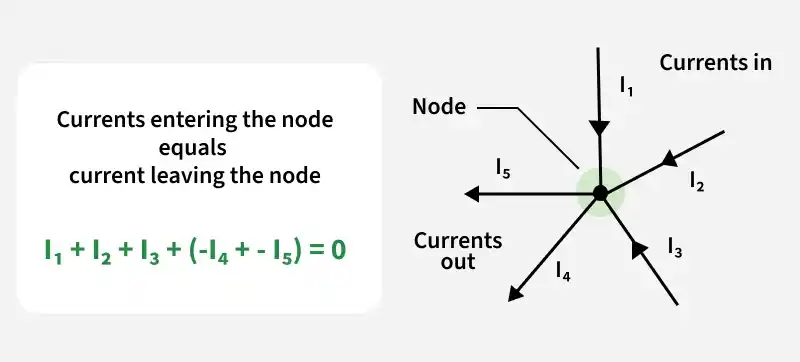
Kirchhoff’s first law is called:
- Junction Law,
- Current Law,
- or KCL (Kirchhoff’s Current Law).
Statement of Kirchhoff’s Current Law
The algebraic sum of currents meeting at a junction is zero.
In simpler words:
Total current entering a junction equals total current leaving the junction.
Mathematically,
Physical Basis of Current Law
Kirchhoff’s current law is based on the principle of conservation of charge. Charge cannot accumulate continuously at a junction.
Therefore:
- whatever charge enters per second,
- must leave per second.
If this did not happen:
- charge accumulation would occur,
- electric potential would continuously increase,
- physical equilibrium would not exist.
Thus KCL is essentially a mathematical expression of charge conservation.
Sign Convention in Current Law
Generally:
- currents entering junction are taken positive,
- currents leaving are taken negative,
or vice versa.
Kirchhoff’s Second Law
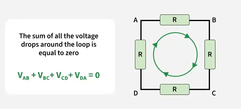
Kirchhoff’s second law is called:
- Loop Law,
- Voltage Law,
- or KVL (Kirchhoff’s Voltage Law).
Statement of Kirchhoff’s Voltage Law
The algebraic sum of all potential differences around any closed loop is zero.
Mathematically,
Physical Basis of Voltage Law
Kirchhoff’s voltage law is based on conservation of energy.
When a charge moves around a closed loop total energy gained must equal total energy lost.
If net energy change were non-zero:
- perpetual energy generation would occur,
- which violates conservation laws.
Hence total emf equals total potential drop.
Potential Rise and Potential Drop
While traversing a loop:
- crossing a cell from negative to positive terminal gives potential rise,
- crossing resistor in direction of current gives potential drop.
1. Across a Cell
From negative to positive terminal: +E
From positive to negative terminal: -E
2. Across a Resistor
Along current direction: -IR
Opposite current direction: +IR
These sign conventions are extremely important in solving circuit problems.
Understanding Potential Drop in a Resistor
A resistor opposes current flow.
As charges move through a resistor:electrical energy converts into heat,electric potential decreases.
Hence current direction always corresponds to decreasing potential inside resistor.
Applying Kirchhoff’s Laws
To solve a circuit:
Step 1:- Assign currents to different branches. Directions may be assumed arbitrarily.
Step 2:- Apply Kirchhoff’s current law at junctions. This gives current relations.
Step 3:- Apply Kirchhoff’s voltage law in independent loops. This gives voltage equations.
Step 4:- Solve simultaneous equations. Unknown currents and voltages are then obtained.
Single Loop Circuit Analysis
Consider a simple circuit containing:
- battery E,
- resistor R,
- current I
Applying KVL:
Hence:
This is essentially Ohm’s law obtained from Kirchhoff’s voltage law.
Multi-Loop Circuit Analysis
Complex circuits may contain:
- several loops,
- shared resistors,
- multiple batteries.
In such cases:
- each independent loop gives one equation,
- junction equations provide additional relations.
Solving them simultaneously yields all unknown currents.
Internal Resistance of a Cell
Real cells possess internal resistance.
Condition:- If
- emf = E,
- internal resistance = r,
- external resistance = R,
then applying KVL:
Thus:
Terminal voltage becomes:
Advantages of Kirchhoff’s Laws
- Applicable to complex circuits
- Works for multiple loops
- Based on fundamental conservation laws
- Systematic analysis possible
- Useful in electronics and instrumentation
- Independent of circuit complexity
Difference Between KCL and KVL
| Kirchhoff’s Current Law | Kirchhoff’s Voltage Law |
|---|---|
| Based on conservation of charge | Based on conservation of energy |
| Applied at junctions | Applied in loops |
| Deals with currents | Deals with voltages |
| Current entering equals current leaving | Total potential rise equals total drop |
Solved Problems
Question 1: Find the value of I from the circuit in the figure below.

Solution: Apply Kirchhoff's First Law to the point P in the supplied circuit.
Consider the sign convention: positive arrows point toward P, whereas negative arrows point away from P.
As a result, we now have the following:
0.2 A – 0.4 A + 0.6 A – 0.5 A + 0.7 A – I = 0
1.5 A – 0.9 A – I = 0
0.6 A – I = 0
I = 0.6A
Question 2: Find the value of the current passing through the resistance R1 = 10 Ω in the circuit below using Kirchhoff's principles, when R2 and R3 both are equal and their value is 5 Ω.
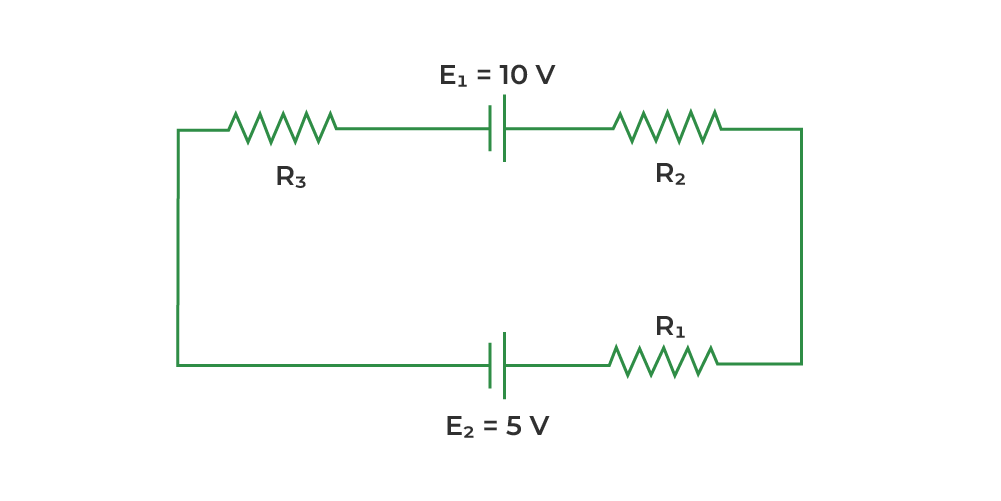
Solution: Applying Kirchhoff's Law in the above circuit, Let's take the current 'i' passing through the loop in the clockwise direction
-10 + 5(i) + 5(i) + 10(i) + 5 = 0
20i -5 = 0
20i = 5
i = 5 / 20 =1/4
The current passing through R1 is 1/4 Ampere.
Unsolved Problems
Question 1: In a circuit, three resistors 4 Ω, 6 Ω, and 12 Ω are connected with a 24 V battery in a loop. Use Kirchhoff’s laws to find the current through each resistor.
Question 2: A circuit has two loops with a 12 V and 6 V battery and resistors 2 Ω, 3 Ω, and 4 Ω arranged in both loops. Find the current in each branch using Kirchhoff’s laws.
Question 3: In a circuit, two resistors 5 Ω and 10 Ω are in one loop, and a 15 Ω resistor is in another loop sharing a common junction. A 30 V battery is connected across the network. Find the current in each resistor using Kirchhoff’s laws.
Question 4: A circuit consists of a 20 V battery connected to a network of three resistors 2 Ω, 4 Ω, and 6 Ω forming two loops. Calculate the current in each resistor using Kirchhoff’s junction and loop rules.
