

Code converters are combinational circuits used to convert data from one binary code to another without changing its numerical value.
- Binary Code represents numbers using weighted binary bits (0s and 1s). It is the standard code used for arithmetic operations and data processing in digital systems.
- Gray Code is a non-weighted binary code in which consecutive values differ by only one bit. It minimizes transition errors and is widely used in position encoders and other reliable digital systems.
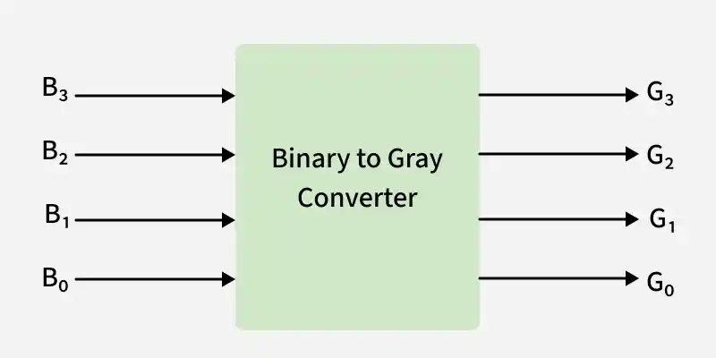
Converting Binary to Gray Code
A Binary-to-Gray converter transforms a binary number into its equivalent Gray code. In Gray code, only one bit changes between two consecutive values, reducing the possibility of errors during bit transitions.
Let B3, B2, B1, and B0 be the binary input bits, where B3 is the Most Significant Bit (MSB) and B0 is the Least Significant Bit (LSB). Similarly, let G3, G2, G1, and G0 be the corresponding Gray code output bits.
The truth table for the Binary-to-Gray conversion is shown below.
| Binary (B3 B2 B1 B0) | Gray Code (G3 G2 G1 G0) |
|---|---|
| 0000 | 0000 |
| 0001 | 0001 |
| 0010 | 0011 |
| 0011 | 0010 |
| 0100 | 0110 |
| 0101 | 0111 |
| 0110 | 0101 |
| 0111 | 0100 |
| 1000 | 1100 |
| 1001 | 1101 |
| 1010 | 1111 |
| 1011 | 1110 |
| 1100 | 1010 |
| 1101 | 1011 |
| 1110 | 1001 |
| 1111 | 1000 |
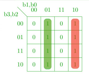
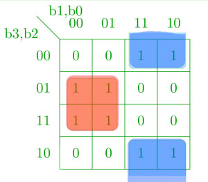
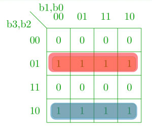
Each Gray code output bit is minimized separately using Karnaugh Maps (K-Maps) to obtain the Boolean expressions required for the corresponding logic circuit.
K-map for g0:
K-map for g1:
K-map for g2:
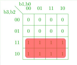
K-map for g3:
Minimized Boolean Expressions and Logic Circuit
g3 = b3
g2 = b3 ⊕ b2
g1 = b2 ⊕ b1
g0 = b1 ⊕ b0
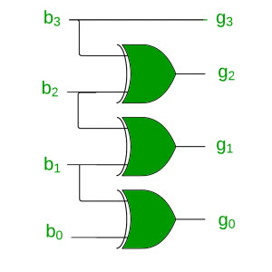
Generalized Boolean Expressions for Binary-to-Gray Conversion
For an n-bit binary number, the Gray code bits are obtained using the following expressions:
gn-1 = bn-1
gi = bi+1 ⊕ bi , for 0 ≤ i < n − 1
Converting Gray Code to Binary
A Gray-to-Binary converter converts a Gray code into its equivalent binary number. Since only one bit changes between successive Gray code values, the original binary number is obtained by successively XORing adjacent Gray code bits.
Let B3, B2, B1, and B0 represent the binary output bits, where B3 is the Most Significant Bit (MSB) and B0 is the Least Significant Bit (LSB). Similarly, let G3, G2, G1, and G0 represent the Gray code input bits.
The truth table for Gray-to-Binary conversion is shown below.
Truth table:
| Gray Code (G3 G2 G1 G0) | Binary (B3 B2 B1 B0) |
|---|---|
| 0000 | 0000 |
| 0001 | 0001 |
| 0011 | 0010 |
| 0010 | 0011 |
| 0110 | 0100 |
| 0111 | 0101 |
| 0101 | 0110 |
| 0100 | 0111 |
| 1100 | 1000 |
| 1101 | 1001 |
| 1111 | 1010 |
| 1110 | 1011 |
| 1010 | 1100 |
| 1011 | 1101 |
| 1001 | 1110 |
| 1000 | 1111 |
Each binary output bit is minimized separately using Karnaugh Maps (K-Maps) to obtain the Boolean expressions for the corresponding logic circuit.
K-map for b0:
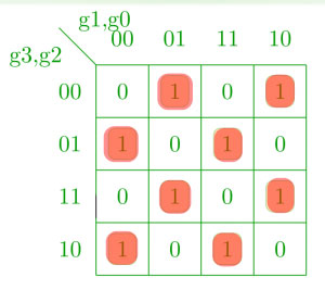
K-map for b1:
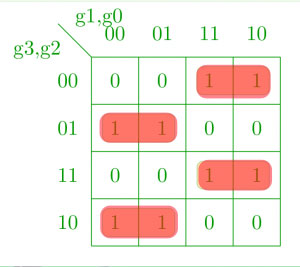
K-map for b2:
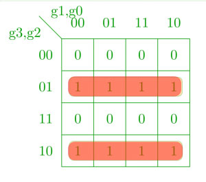
K-map for b3:
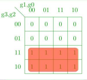
Minimized Boolean Expressions and Corresponding Logic Circuit
b3 = g3
b2 = g3 ⊕ g2
b1 = g2 ⊕ g1
b0 = g1 ⊕ g0
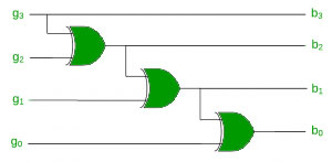
Generalized Boolean Expressions for Gray-to-Binary Conversion
For an n-bit Gray code, the corresponding binary bits are obtained using the following expressions:
bn-1 = gn-1
bi = bi+1 ⊕ gi , for 0 ≤ i < n − 1
Applications
- Rotary Encoders: Converts the Gray code output of rotary encoders into binary for digital processing.
- Control Systems: Enables reliable data conversion between binary and Gray code in digital control systems.
- Signal Processing: Used to translate data between binary and Gray code for accurate signal processing.
- Analog-to-Digital Conversion (ADC): Converts Gray code outputs of ADCs into binary for use by processors and digital circuits.
