

A multiplexer (MUX) is a combinational digital circuit that selects one of several input signals and forwards it to a single output based on the values of the selection lines. A mux needs n select lines to control 2n inputs.
- Multiplexers are also known as N-to-1 selectors.
- They are referred to as parallel-to-serial converters.
- Also called many-to-one circuits and universal logic circuits.
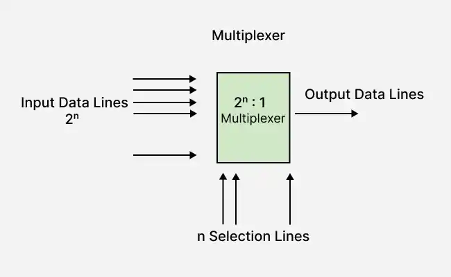
Types of Mux
Multiplexers can be classified into different types based on the number of input lines. The two most commonly used types are:
- 2 x 1 Mux
- 4 x 1 Mux
2x1 Multiplexer
A 2:1 multiplexer (MUX) is a combinational circuit that has two input lines (I₀ and I₁), one select line (S₀), and one output (Y). The select line determines whether I₀ or I₁ appears at the output.
Block Diagram of 2:1 Multiplexer with Truth Table
The block diagram and truth table of a 2:1 multiplexer are shown below. Here, I₀ and I₁ are the input lines, S₀ is the select line, and Y is the output line.
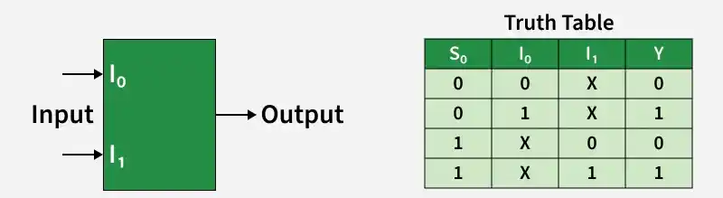
The output of the 2:1 multiplexer depends on the value of the select line S₀:
- When S₀ = 0, input I₀ is selected and passed to the output (Y).
- When S₀ = 1, input I₁ is selected and passed to the output (Y).
Logical Expression of 2x1 Mux
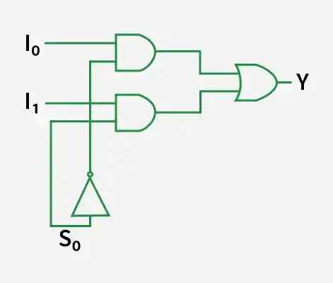
From the truth table, the Boolean expression of the 2:1 multiplexer is:
Y=\overline{S_0}.I_0+S_0.I_1
Circuit Diagram of 2x1 Multiplexers
The circuit diagram corresponding to the above Boolean expression is shown below.
4×1 Multiplexer
A 4:1 multiplexer (MUX) is a combinational digital circuit with four input lines (I₀, I₁, I₂, and I₃), two select lines (S₀ and S₁), and one output (Y). The values of the select lines determine which input is forwarded to the output.
Block Diagram of 4×1 Multiplexer
The block diagram of a 4:1 multiplexer is shown below. Here, I₀, I₁, I₂, and I₃ are the input lines, S₀ and S₁ are the select lines, and Y is the output line.
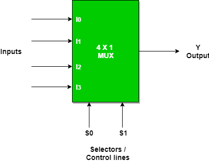 The output of the 4:1 multiplexer depends on the binary combination of the select lines (S₁S₀):
- When S₁S₀ = 00, input I₀ is selected and passed to the output (Y).
- When S₁S₀ = 01, input I₁ is selected and passed to the output (Y).
- When S₁S₀ = 10, input I₂ is selected and passed to the output (Y).
- When S₁S₀ = 11, input I₃ is selected and passed to the output (Y).
Truth Table of 4×1 Multiplexer
The truth table of a 4:1 multiplexer is shown below. It describes how the combination of the select lines (S₀ and S₁) determines which input (I₀, I₁, I₂, or I₃) is connected to the output (Y).
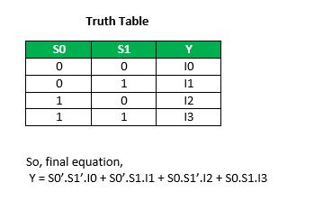
From the truth table, the Boolean expression of the 4:1 multiplexer is:
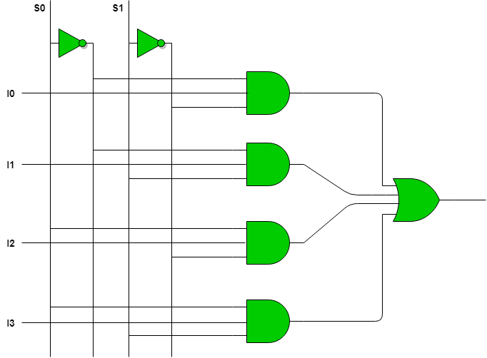
Y=S1S0I0+S1S0I1+S1S0I2+S1S0I3
Circuit Diagram of 4:1 Multiplexer
The circuit diagram corresponding to the above Boolean expression is shown below.
Advantages
- Efficient Data Selection: A multiplexer selects one input from multiple input lines using select lines, simplifying data transmission.
- Reduced Hardware Complexity: It reduces the number of logic gates and interconnections required in digital circuits.
- Cost-Effective Design: A single multiplexer can replace multiple switching circuits, reducing the overall implementation cost.
Disadvantages
- Propagation Delay: The output may experience a slight delay due to internal switching and logic gate operations.
- Additional Select Lines: Larger multiplexers require more select lines, increasing circuit complexity.
- Single Output: A multiplexer can transmit only one selected input to the output at a time.
Applications
- Data Routing: Routes one of several input data lines to a single output based on the values of the select lines.
- Communication Systems: Enables multiple signals to share a single communication channel, improving bandwidth utilization and reducing transmission cost.
- Microprocessors and Memory: Supports data selection and address decoding for efficient data transfer and memory access.
Also Check
- Implementation of Different Gates with 2:1 Mux
- Implementation of Higher Order MUX using Lower Order MUX
- Demultiplexer(DEMUX)
