

A Full Subtractor is a combinational circuit used to subtract three single-bit binary inputs: Minuend (A), Subtrahend (B), and Borrow-in (B-IN). It produces two outputs: Difference (D) and Borrow-out (B-OUT). Unlike a Half Subtractor, it can handle the borrow generated from the previous stage, making it suitable for multi-bit binary subtraction.
- Can be cascaded to perform subtraction of multi-bit binary numbers.
- Forms the basic building block of binary subtraction circuits.

Truth Table of Full Subtractor
The following truth table shows the outputs Difference (D) and Borrow-out (B-OUT) for all possible combinations of the three inputs: A (Minuend), B (Subtrahend), and Borrow-in (B-IN). This table is used to derive the Boolean expressions and K-Maps for the Difference and Borrow-out outputs.
Input | Output | |||
|---|---|---|---|---|
A | B | Bin | D | Bout |
0 | 0 | 0 | 0 | 0 |
0 | 0 | 1 | 1 | 1 |
0 | 1 | 0 | 1 | 1 |
0 | 1 | 1 | 0 | 1 |
1 | 0 | 0 | 1 | 0 |
1 | 0 | 1 | 0 | 0 |
1 | 1 | 0 | 0 | 0 |
1 | 1 | 1 | 1 | 1 |
K-Map for Full Subtractor
From the truth table, separate K-Maps are drawn for the Difference (D) and Borrow-out (B-OUT) outputs. These K-Maps help simplify the Boolean expressions by grouping adjacent 1s.
Difference (D)
The Boolean expression for the Difference output obtained from the K-Map is:
D = A'B'BIN + A'BB'IN + AB'B'IN + ABBIN
Grouping the common terms gives:
D = BIN(A'B' + AB) + B'IN(AB' + A'B)
Using the identities A'B' + AB = A XNOR B and AB' + A'B = A XOR B:
D = BIN(A XNOR B) + B'IN (A XOR B)
After simplification:
D = (A ⊕ B) ⊕ BIN

Borrow (B)
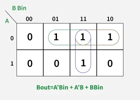
The Boolean expression for the Borrow-out BOUT output obtained from the K-Map is:
BOUT = A'B'BIN + A'BB'IN + A'BBIN + ABBIN
Factoring the common terms gives:
BOUT = A'BIN(B + B') + A'B(BIN + B'IN) + BBIN(A + A')
Using the identities B′IN + BIN = 1 and A′B′ + AB = A XNOR B, the expression becomes:
BOUT = A'B + BIN(A XNOR B)
After simplification:
BOUT = A'B + A'BIN + BBIN
Logic Circuit for Full Subtractor
A Full Subtractor can be implemented using two XOR gates, two AND gates, one NOT gate, and one OR gate. The XOR gates generate the Difference (D) output, while the AND, NOT, and OR gates work together to produce the Borrow-out (B-OUT) output.
- First XOR Gate: Computes A ⊕ B.
- Second XOR Gate: Combines (A ⊕ B) with B-IN to generate the final Difference (D).
For the borrow output:
- NOT Gate: Generates the complement of A (A').
- First AND Gate: Computes A' · B.
- Second AND Gate: Computes B-IN · (A ⊕ B)'.
- OR Gate: Combines the outputs of both AND gates to generate the final Borrow-out (B-OUT).

Implementation of Full Subtractor using Half Subtractors
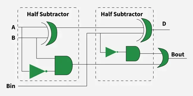
A Full Subtractor can be implemented using two Half Subtractors and one OR gate. The first Half Subtractor subtracts B from A, producing an intermediate Difference and Borrow. The intermediate Difference is then combined with the Borrow-in (B-IN) by the second Half Subtractor to generate the final Difference (D). Finally, the Borrow outputs from both Half Subtractors are combined using an OR gate to produce the final Borrow-out (B-OUT), as shown in the diagram below.
Applications
- Arithmetic Circuits: Used to subtract binary numbers in digital arithmetic operations.
- Arithmetic Logic Units (ALUs): Performs subtraction operations inside processors and microcontrollers.
- Digital Computers: Used in CPUs and other digital systems where binary subtraction is required.
- Comparators: Helps determine the relationship between binary numbers during comparison operations.
- Multi-bit Subtractors: Acts as the basic building block for designing ripple borrow and other multi-bit subtractor circuits.
