

A D (Data) flip-flop is a digital memory circuit that stores a single bit of binary data. It has one data input (D), one clock input (CLK) and two complementary outputs (Q and Q′).
- It copies the input D to the output Q only at the active clock edge.
- It avoids the invalid (S = R = 1) state of the SR flip-flop, since it uses only one data input.
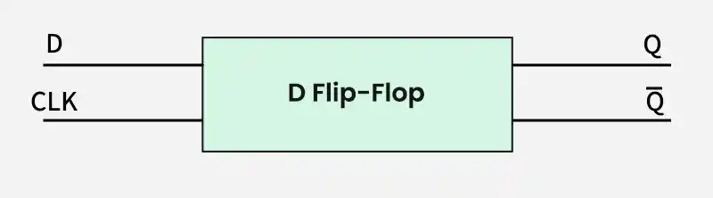
Working of D Flip Flop
A D flip-flop copies the value of D to Q at the active clock edge and holds it until the next active edge.
- D = 0: Q becomes 0 at the active clock edge.
- D = 1: Q becomes 1 at the active clock edge.
- Between clock edges, Q holds its value and ignores changes in D.
- Q′ is always the complement of Q.
Truth Table of D Flip-Flop
| D | CLK | Qₙ₊₁ |
|---|---|---|
| 0 | ↑ (Rising edge) | 0 |
1 | ↑ (Rising edge) | 1 |
| X | No active edge (0, 1 or ↓) | Qₙ (no change) |
Characteristic Table of D Flip Flop
The characteristic table shows the next state (Qₙ₊₁) for each combination of the input (D) and the present state (Qₙ).
| D | Qₙ (Current) | Qₙ₊₁ (Next) |
|---|---|---|
| 0 | 0 | 0 |
| 0 | 1 | 0 |
| 1 | 0 | 1 |
| 1 | 1 | 1 |
The next state depends only on D, not on the present state.
Characteristic Equation
The characteristic equation represents the next state (Qn+1) of the D flip-flop in terms of the input (D).
Characteristic Equation: Qn+1 = D
- Qn+1 is the next state of the flip-flop.
- The next state is always equal to the input D at the active clock edge.
D Flip Flop Excitation Table
The excitation table shows the input D required to move the flip-flop from the present state (Qₙ) to the next state (Qₙ₊₁).
| Qₙ | Qₙ₊₁ (Next) | D (Required) |
|---|---|---|
| 0 | 0 | 0 |
| 0 | 1 | 1 |
| 1 | 0 | 0 |
| 1 | 1 | 1 |
The required D is always equal to the desired next state.
Construction of D Flip Flop
A D flip-flop is built from two D latches connected in series, called the master and the slave, with inverted enable (clock) signals.
- When CLK is low, the master latch is transparent and follows D, while the slave holds the old value.
- When CLK is high, the master holds its value and the slave passes it to Q.
- So Q changes only at the clock edge.
D Latch vs D Flip Flop
| Feature | D Latch | D Flip Flop |
|---|---|---|
| Triggering | Level-triggered | Edge-triggered |
| Output changes | Any time the enable is active | Only at the clock edge |
| Construction | Single gated latch | Two latches (master-slave) |
Applications of D Flip Flop
- Registers: Store multi-bit data, with one flip-flop per bit.
- Counters: Count events in digital systems.
- Memory elements: Hold data in synchronous circuits.
- Synchronization: Align asynchronous inputs to a clock.
